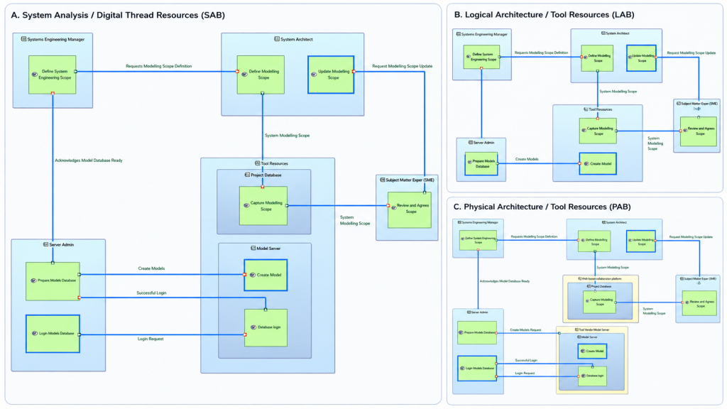
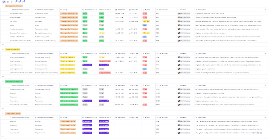
When a new Model-Based System Architecture (MBSE) model or during the system architecture modelling development, stakeholders involved or with an interest on, may ask and express different understandings and modelling expectations:
- What modelling activities and artefacts content should be produced?
- What are the artefacts relationships and traceability?
- What are the stakeholder roles involved for the modelling effort?
- What is the flow between processes?
- What should be the scope of the model?
The simple process for architecture development has been defined to architect and deliver by managing stakeholder expectations, and described on this article.
This process was inspired by the process modelling content within ‘SysML for Systems Engineering’ book, the MBSE with Arcadia step-by-step guide and the MagicGrid framework.
Capturing process development and definition goals
- Address stakeholder understanding and expectations; capture and define roles, activities, and artefacts.
- Ease of use; ensure ease of use, in terms of speed of understanding, adoption and complexity.
- Clear communication; clearly communicate modelling efforts and manage stakeholder expectations
- Level of abstraction; capture appropriate level of information
- Consistency; ensure consistency with modelling framework adopted
Process in one page
The process starts with the set of stakeholder needs captured by the requirements engineer in a specification captured either on an external Requirements Management Tool (RMT), step 1. Needs and requirements can be captured directly in the MBSE modelling tool. If needs/requirements are captured in an external tool, there is the need to import them into the modelling tool and feed the start of the conceptual architecture analysis..
The conceptual architecture analysis follows the MagicGrid framework steps and is executed by the system architect and normally supported by a Subject Matter Expert (SME), to capture domain knowledge. This process is flexible enough to work with any other MBSE framework or method, for example the Arcadia method. It is strongly advised to discuss, agree and clarify the modelling effort with all stakeholder involved to promote communication and manage modelling expectations. When the system architect completes the conceptual architecture, it can be exported from the modelling tool (step 2) containing the agreed set of diagrams and description.
The requirements engineer at the system level receives as input both the needs and the model document supporting and enhancing the SPP textual requirements captured at the system level (step 3).
The model provides the analytical reasoning linking requirements (design view) to needs (stakeholder view) and incorporating SME domain knowledge not present in the needs. The process is repeated for the solution and subsystem capture.
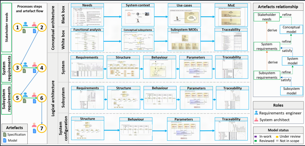
Next sections it will be described in detail each session of the process definition in one page.

This document contains:
- Simple Process for Architecture Development with MagicGrid focused on the solution architecture.
- References to content and resources
Roles definition
Roles involved in the modelling process were identified and defined. This allowed the identification of new roles and associated training needs within the organisation. There is not a 1:1 mapping between role and person for the following reasons:
- Requirements engineer; responsible to capture stakeholder needs and requirements.
- System architect; captures the system architecture for a system-of-interest. A system is normally decomposed in several layers of abstraction; hence, it is expected system architects to work in a collaborative environment.
- Subject Matter Expert; subject matter expert responsible for a product development, e.g., fuel cycle. He is also responsible to review the model content.

Artefacts relationship
This section identifies and captures artefacts, and relationship.
Capturing process artefacts guides and supports stakeholders involved in understanding the relationship and traceability in the model-based approach. The list of artefacts currently captured:
- Stakeholder needs. Captures the initial textual stakeholder needs.
- System and subsystem requirements. Captures system textual requirements at the different levels.
- Conceptual, system and subsystem architecture model. Model tool file containing the architecture.
It is, very important to understand the artefacts relationship and structure. The below figure is used to show and describe to all stakeholders what different types of traceability are expected, that is, between textual needs and between the needs and requirements and the architecture.
The “derive” traceability between textual needs and requirements are captured, reviewed and managed in the RMT, and not part of the system architecture process, hence, not described.
The “refine” and “satisfy” traceability relationship are captured in the MBSE modelling tool.

Activities and modelling artefacts content
Within each process step shown in figure MBSE process above there are a number of activities executed by the system architect to produce artefacts. A visual representation facilitates understanding with stakeholders and assists in the discussion and agreement of scope. Artefacts are a combination of SysML diagrams and additional tool diagrams, tables, and matrices. Maturity of both process tasks and artefacts is captured to assist with both capability and artefact development. The activities produce a set of artefacts are shown in figure below as example for the conceptual architecture:

Steps and artefact flow between processes
The “steps and artefact flow between processes” captures the interaction between cross-disciplinary processes, that is, system requirements definition process, step 1, 3 and step 5 and the system architecture definition process steps 2, 4, 6 and 7. It also shows the high-level artefacts produced and consumed by each of the process:
- Requirements definition process produces stakeholder needs and requirements captured in a specification and the Requirements Management Tool (RMT) adopted, that is represented by the green icon next to the blue human.
- System architecture process consumes artefacts from requirements process and produces modelling artefacts, such as model files or report document captured in an office tools, blue icon and pink human. The artefact content for the system architecture was already described previously in the content view.
This view shows a “Zig-Zag” flow from top level stakeholder needs to lower-level and subsystem architecture development, proving its value to:
- Where to start modelling, a system architect capturing the architecture for a subsystem, step 6, shall start by looking at the requirements captured in step 5 and the model captured during step 4 activities.
- When planning activities or presenting to non-System Engineer, what is the modelling effort involved, roles and artefacts consumed and produced.

Process usage in a modelling tool
The process above has been used in real projects and for the MBSE Cameo modelling tool. The below image is an example for the conceptual architecture capture:
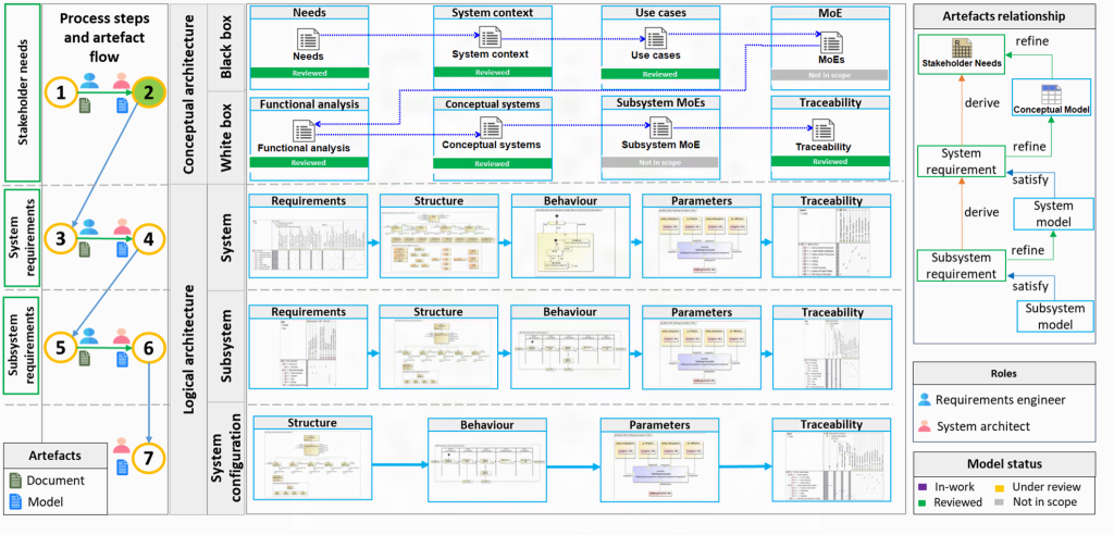
Presentations delivered in Cameo modelling tool
Using the simple process for architecture development templates tailored to a conceptual architecture, solution and configuration, presentations can be delivered directly in the tool. Below a template demo within the Cameo modelling tool:
A system architect can move forward and backwards in a Cameo content diagram similar to a office presentation. No longer the need to export diagrams and increased workload to keep diagrams and model synched.
Key takeaways
The process described above and being used in projects has proven its value to:
- Tackle early modelling lack of understanding.
- Supports identification of roles and associated training needs.
- Clearly communicate modelling efforts and manage stakeholder expectations.
- Shows and clarifies artefacts between processes relationship.
- Clear step-by-step guidance between processes and artefacts flow.
- Clarify and support scope architecture development and agreement.
- Enables modellers to architect by guiding and clarifying which artefacts are produced and consumed throughout development.
- Manage and deliver against stakeholder expectations.
This process was sponsored by UKAEA.